

Biologically-Inspired Running Robot
Biologically-Inspired Fast Running Robot
(Tokyo Institute of Technology 1998-2001, 2005-, Tohoku Univ. 2002-2004, Ritsumeikan Univ. 2010-)
Objective
In this study, we aim to investigate the running mechanism of animals by engineering approach.
In a gravity field, animals must bear ground force that is greater than twice their weight. Moreover, they receive a large impulse at touchdown.
As many biomechanists have indicated, tendons play an important role in running or jumping motion. They store kinetic energy as potential energy during stance and also absorb the impulse at touchdown.
To realize a running robot, introducing such springy characteristics into leg design is quite natural.
Pioneering work was done by Raibert and co-workers. They developed one-legged, biped, and quadruped running robots; all of them had springy legs of telescopic type, and realized various running motions.
Motivated from above studies, we proposed a new alternative leg model for high-speed running.
Our approach was to ``import" biomechanical studies on running animal into mechanical design.
In those studies, we especially focused on the geometric alignment of the muscle-tendon system of ankle joint and its function.
Specifically, we introduced a spring as the bi-articular muscle to drive the ankle joint.
One-legged running robot; Kenken
1) Overview
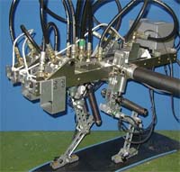
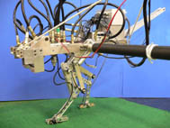
A prototype hardware of one-legged running robot, named Kenken was developed in 1999.
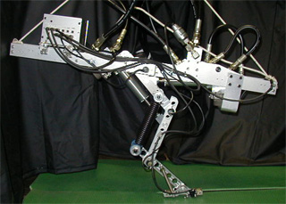
Biologically-inspired hopping rorobot: Kenken
The robot has articulated leg composed of three links, and uses two hydraulic actuators as muscles and linear springs as a tendon.
The mass of the leg is relatively large: 3.6 kg. Individual masses of the thigh, shank, and foot are 2.42 kg, 0.75 kg, and 0.43 kg, respectively.
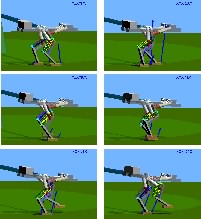
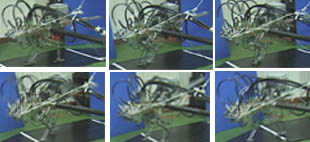
Using an empirical controller based on the uncontrolled dynamics of our model, the robot has succeeded in running of several steps in a plane.
Successful one-legged hopping experiments showed that our leg mechanism is actually effective for running.
More specifically, the leg spring attached as a bi-articular muscle (gastrocnemius or plantaris) enables the robot to produce sufficient propulsion force by virtue of an energy transfer from the knee, even if there is no actuator at the ankle joint.
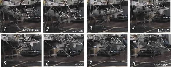
Experiment of high-speed hopping
2) About the new leg mechanism
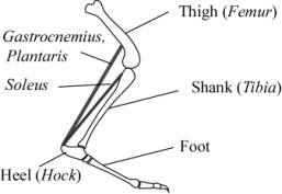
Figure shows extensors of an ankle joint, which play the main role in running.
Among them, this study specifically examined arrangement of the bi-articular muscle groups, gastrocnemius and plantaris.
Then, the new leg model shown in Fig. was proposed.
It is an articulated leg model composed of three links.
It has two active joints, the hip and knee, and one passive joint, the ankle; there is no actuator at its foot (this means the toe can rotate on the ground during stance phase, acting as a free pivot).
  |
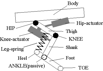  |
| Musculo-skeletal system of dog ankle | New leg model |
The most distinctive feature of this model is arrangement of the leg spring.
The leg spring is attached between the thigh and heel parallel to the shank.
Arrangement of the leg spring in this way creates the following two important effects during hopping:
- During supporting phase, holding the knee joint enables the leg spring to absorb a large impulse at touchdown and to transfer its kinetic energy to potential energy for the next stride. Extending the knee yields an extra displacement of the spring; hence it adds potential energy to the spring.
- During swing phase, the spring constitutes a member of ``parallel four-bar linkage" because compressive force to the spring is not so large at that duration. Consequently, it enables passive retraction and extension of the leg, provided the inertia of the links is chosen appropriately.
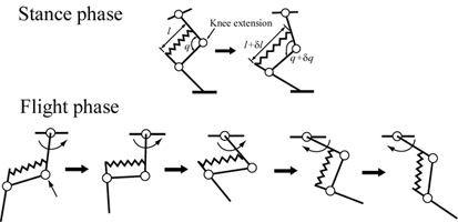  |
| Leg operation |
3) Experimental system
Since running requires relatively high energy and always accompanies shock against the ground, joint actuation is the most critical problem for hardware realization.
We developed a small and lightweight servo actuator, directly mounted with an industry servovalve.
On-board sensors are, six potentiometers at each joint, and foot switches.
We also installed accelerometers and pressure sensors, which is used only for measurement.
Aluminum box attached to the rear includes, interface circuit, servo amplifier, and signal conditioning circuit, which were hand-made with taking impulse and vibration into accounts.
  |
 |
| Experimental setup |
We developed experimental setup shown in the above figure.
A tether boom constrains the robot to the sagittal plane and measures the horizontal position, vertical position, and pitch angle of the body via three optical encoders.
It also carries hydraulic hoses, signal line, and DC line.
An aluminum box attached to the rear includes an interface circuit, servo amplifier, and signal conditioning circuit, which were hand-made taking the impulses and vibrations into account.
The control program is written in MATLAB/SIMULINK code and runs in a single timer task with a 0.5 ms sampling period.
4) 3D simulation
It is difficult to derive the controller in a systematic way because the robot has the quite complex nonlinear dynamics described below:
- (Under-actuated system) The robot has an articulated leg with a passive joint; it has no actuator at its sole.
- (Hybrid system) Dynamics of the robot change drastically while the robot transits through to a stance phase, flight phase, touchdown, etc.
- (Periodic system) Linearisation around equilibrium points and stabilisation has no meaning; instead, their orbital stability is needed.
Therefore, as the first attempt, the controller was designed empirically based on analysis of the characteristic dynamics of the robot.
A precise simulator was constructed for this purpose.
Matlab-based graphical programming was introduced for flexibility and rapid prototyping of the controller.
Specifically, the mechanical model of the robot and contact model with the ground was constructed using DADS (http://www.lms.be/); also, the hydraulic actuator was modeled as general electro-hydraulic system using SIMULINK.
Simulation of steady hopping at 1[m/s] (AVI 1.61MB)
 The figure shows a block diagram of the simulator.
The dashed line indicates the simulation model described below.
If the simulation model is replaced by an actual mechanical model through the sensor input/output interface, the controllers developed and estimated on the simulator can be applied immediately to the actual robot.
5) Experimental results
- Joint driving test on a testbed [MPG 1053K]
- Steady vertical hopping) [MPG 576K].
- Steady running at 0.5[m/s]) [MPG 991K].
- Steady running at 1.0[m/s] [MPG 389K].
- Running toward 1.5[m/s] [MPG 529K]
- High speed running 2.0[m/s] [MPG 811K]
- Just for fun [MPG 800K]
Biped running robot ; KenkenII
 |
 |
| KenkenII | Walking simulation |
As a direct extension of Kenken, we developed a new planar biped robot, named KenkenII, to realize not only hopping, but also biped walking and running.
Preliminary experimental results
- Joint driving of KenkenII [MPG 887K]
- Jumping test at the one-third pressure (7MPa) [MPG 568K]

1. Biped running robot ; KenkenIIR
 |
 |
| KenkenIIR | Walking experiment with an active tail |
To enlarge the region of attraction, an active tail was introduced into KenkenII in 2004.
Jumping test (one-third of the maximum power)
Fast swing test
5. Reference
- S. Hyon, T. Emura and T. Mita, Dynamics-based control of one-legged hopping robot, Journal of Systems and Control Engineering, Proceedings of the Institution of Mechanical Engineers Part I, pp. 83-98, 2003.
- S. Hyon, S. Abe and T. Emura , Development of a biologically-inspired biped robot KenkenII, Proc. of 6th Japan-France Congress on Mechatronics & 4th Asia-Europe Congress on Mechatronics, pp.404-409, Sep, 2003.
- S. Hyon, S. Kamijo and T. Mita, A biologically inspired hopping robot -Kenken, Trans. of RSJ, , vol.20, no.4, pp.453-462, 2002 (in Japanese).
- S. Hyon and T. Mita, Development of a biologically inspired hopping robot -Kenken, Proc. of IEEE ICRA, pp. 3984-3991, 2002.
6. Acknowledgement
The research on Kenken was supported by the Grant-in-Aid for COE Research Project supported by the Ministry of Education,Science, Sports and Culture, JAPAN.
2020/06/11